
TM 5-3805-294-23-4
0628
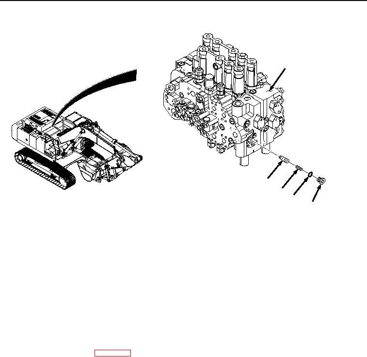
INSTALLATION - Continued
3
5
4
2
1
HYEX03371
Figure 2.
Check Valve Installation.
2.
Using a twisting motion, install poppet (Figure 2, Item 5) to control valve (Figure 2, Item 3).
3.
Install spring (Figure 2, Item 4) to control valve (Figure 2, Item 3).
4.
Lightly lubricate O-ring (Figure 2, Item 2) with clean oil.
5.
Install O-ring (Figure 2, Item 2) to plug (Figure 2, Item 1).
6.
Install plug (Figure 2, Item 1) and O-ring (Figure 2, Item 2) to control valve (Figure 2, Item 3).
END OF TASK
FOLLOW-ON MAINTENANCE
1.
Install right travel and bucket combined function check valve. (Volume 5, WP 0731)
2.
Install center top cover. (WP 0589)
3.
Perform the Standard Follow-On Maintenance Instructions. (Volume 3, WP 0384)
END OF TASK
END OF WORK PACKAGE