
TM 5-3805-294-23-4
0629
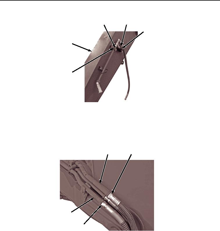
ARM REMOVAL - Continued
61, 62
58, 59
63
14
60
HYEX02282
Figure 20. Left Attachment Valve Removal.
49.
Remove two bolts (Figure 20, Item 61), washers (Figure 20, Item 62), and valve assembly (Figure 20, Item 63)
from arm (Figure 20, Item 14).
50.
Remove hose (Figure 21, Item 64) and O-ring (Figure 21, Item 65) from line (Figure 21, Item 66). Discard O-
ring.
66
64, 65
69
61, 68
HYEX02283
Figure 21. Right Side Arm Hose Removal.
51.
Remove hose (Figure 21, Item 67) and O-ring (Figure 21, Item 68) from line (Figure 21, Item 69). Discard O-
ring.
52.
Remove bolt (Figure 22, Item 70), washer (Figure 22, Item 71), bracket (Figure 22, Item 72), and clamp (Figure
22, Item 73) from arm (Figure 22, Item 14).