
TM 5-3805-294-23-4
0629
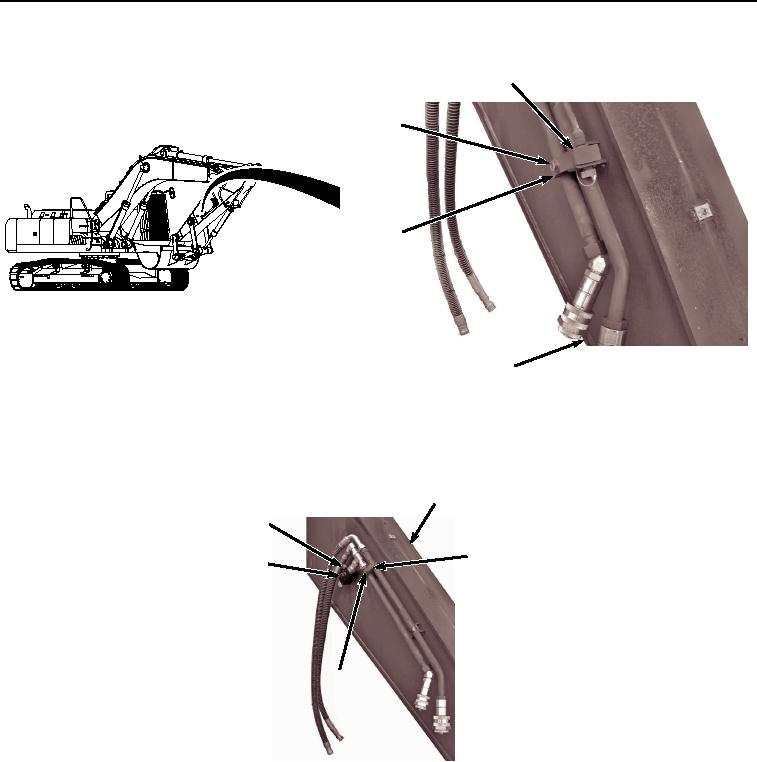
ARM REMOVAL - Continued
72
70, 71
73
14
HYEX02284
Figure 22.
Clamp Removal.
53.
Remove bolt (Figure 23, Item 74), washer (Figure 23, Item 75), and clamp (Figure 23, Item 76) from arm (Figure
23, Item 14).
14
77, 78
76
79
74, 75
HYEX02285
Figure 23.
Right Attachment Valve Removal.
54.
Remove two bolts (Figure 23, Item 77), washers (Figure 23, Item 78), and valve assembly (Figure 23, Item 79)
from arm (Figure 23, Item 14).
55.
Install suitable lifting devices (Figure 24, Item 25) and (Figure 24, Item 80) to arm (Figure 24, Item 14).