
TM 5-3805-294-23-4
0629
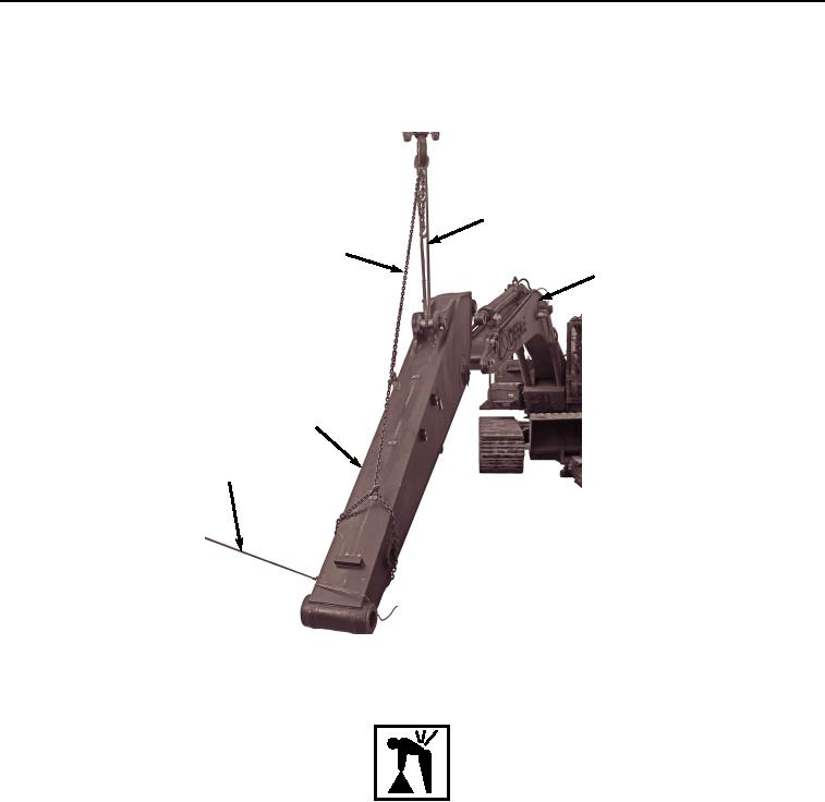
INSTALLATION - Continued
2.
Attach tag line (Figure 29, Item 1) and suitable lifting devices (Figure 29, Items 25 and 80) to arm (Figure 29,
Item 14).
25
80
27
14
1
HYEX02289
Figure 29.
Arm Installation.
WARNING
Arm weighs approximately 1865 lb (846 kg). Do not attempt to lift or move without the aid of
assistants and suitable lifting device. Failure to comply may result in injury or death to
personnel.
3.
With the aid of assistants, tag line (Figure 29, Item 1), and suitable lifting devices (Figure 29, Items 25 and 80),
position arm (Figure 29, Item 14) to boom (Figure 29, Item 28).
4.
Install two shims (Figure 29, Item 85) between boom (Figure 29, Item 27) and arm (Figure 29, Item 14).
5.
Lightly lubricate arm pin (Figure 30, Item 84) with clean grease.