
TM 5-3805-294-23-4
0629
INSTALLATION - Continued
15.
Install hose (Figure 35, Item 64) and O-ring (Figure 35, Item 65) to line (Figure 35, Item 66).
16.
Install valve assembly (Figure 36, Item 63) to arm (Figure 36, Item 14) with two bolts (Figure 36, Item 61) and
washers (Figure 36, Item 62).
61, 62
58, 59
63
14
60
HYEX02282
Figure 36. Left Attachment Valve Installation.
17.
Install two clamps (Figure 36, Item 60) to arm (Figure 36, Item 14) with two bolts (Figure 36, Item 58) and
washers (Figure 36, Item 59).
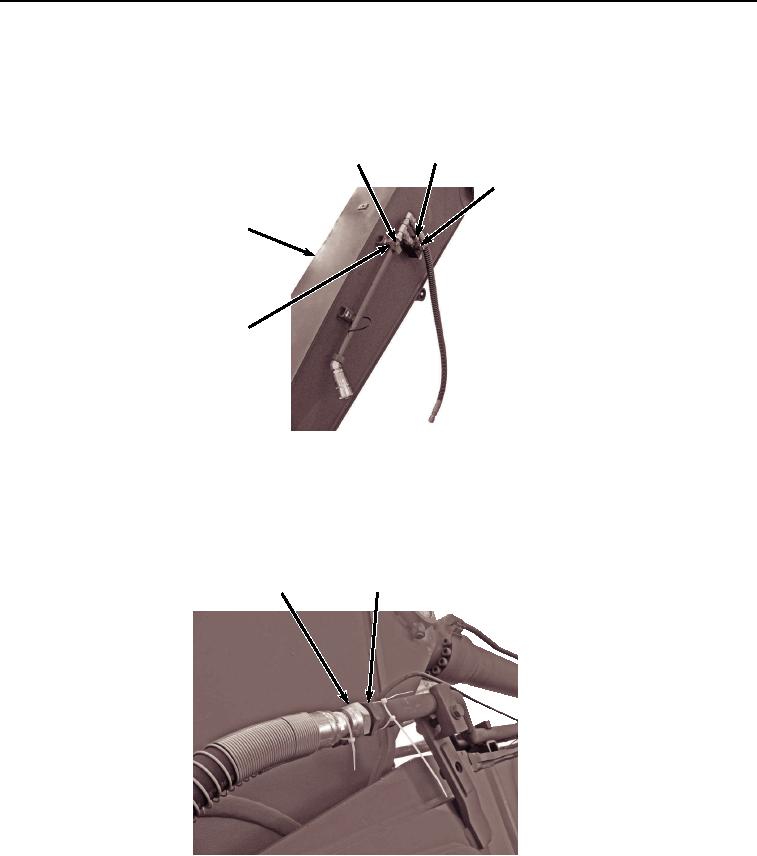
18.
Lightly lubricate O-ring (Figure 37, Item 56) with clean oil.
55, 56
57
HYEX02281
Figure 37.
Left Side Arm Hose Installation.
19.
Install hose (Figure 37, Item 55) and O-ring (Figure 37, Item 56) to line (Figure 37, Item 57).
20.
Install solenoid valve (Figure 38, Item 50) and cover (Figure 38, Item 54) to arm (Figure 38, Item 14) with two
bolts (Figure 38, Item 51), lockwashers (Figure 38, Item 52), and washers (Figure 38, Item 53).