
TM 5-3805-294-23-4
0632
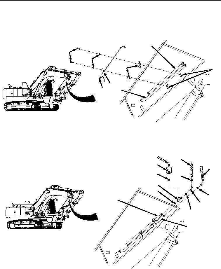
RIGHT SIDE AUXILIARY CIRCUIT ARM LINES INSTALLATION - Continued
1.
Install line (Figure 3, Item 2) and line (Figure 3, Item 11) to arm (Figure 3, Item 18) with cap (Figure 3, Item
17), two brackets (Figure 3, Item 16), bracket (Figure 3, Item 15), two washers (Figure 3, Item 14), and bolts
(Figure 3, Item 13).
11
13
14
16
18
15
17
2
HYEX01127
Figure 3.
Lines Installation.
2.
Lightly lubricate O-ring (Figure 4, Item 12) with clean oil.
4
9
1
10
6
7
12
3
11
5
8
2
HYEX01114
Figure 4.
Hoses and Fittings Installation.
3.
Install O-ring (Figure 4, Item 12) to line (Figure 4, Item 11).