
TM 5-3805-294-23-4
0632
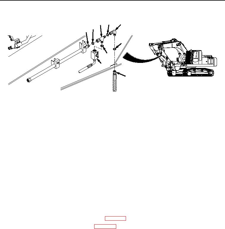
LEFT SIDE AUXILIARY CIRCUIT ARM LINES INSTALLATION - Continued
22 23
20
27
26
21
25
24
19
HYEX01115
Figure 8.
Hose and Fittings Installation.
3.
Install O-ring (Figure 8, Item 27) to line (Figure 8, Item 26).
4.
Install fitting (Figure 8, Item 22) to line (Figure 8, Item 26).
5.
Lightly lubricate O-ring (Figure 8, Item 25) with clean oil.
6.
Install O-ring (Figure 8, Item 25) to fitting (Figure 8, Item 22).
7.
Install fitting (Figure 8, Item 22) to auxiliary circuit shut-off valve (Figure 8, Item 24).
8.
Lightly lubricate O-ring (Figure 8, Item 23) with clean oil.
9.
Install O-ring (Figure 8, Item 23) to fitting (Figure 8, Item 22).
10.
Install fitting (Figure 8, Item 20) to fitting (Figure 8, Item 22).
11.
Lightly lubricate O-ring (Figure 8, Item 21) with clean oil.
12.
Install O-ring (Figure 8, Item 21) to fitting (Figure 8, Item 20).
13.
Install hose (Figure 8, Item 19) to fitting (Figure 8, Item 20).
END OF TASK
FOLLOW ON MAINTENANCE
1.
Install auxiliary circuit quick disconnect fittings. (WP 0636)
2.
Release vacuum from hydraulic reservoir. (WP 0620)
3.
Perform the Standard Follow-On Maintenance Instructions. (Volume 3, WP 0384)
END OF TASK
END OF WORK PACKAGE