
TM 5-3805-294-23-4
0632
RIGHT SIDE AUXILIARY CIRCUIT ARM LINES REMOVAL - Continued
4.
Remove O-ring (Figure 1, Item 6) from fitting (Figure 1, Item 5). Discard O-ring.
5.
Remove fitting (Figure 1, Item 5) from fitting (Figure 1, Item 7).
6.
Remove O-ring (Figure 1, Item 8) from fitting (Figure 1, Item 7). Discard O-ring.
7.
Remove fitting (Figure 1, Item 7) from auxiliary circuit shut-off valve (Figure 1, Item 9).
8.
Remove O-ring (Figure 1, Item 10) from fitting (Figure 1, Item 7). Discard O-ring.
9.
Remove fitting (Figure 1, Item 7) from line (Figure 1, Item 11).
10.
Remove O-ring (Figure 1, Item 12) from line (Figure 1, Item 11). Discard O-ring.
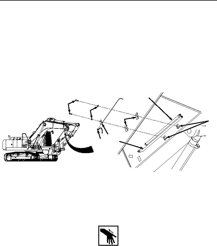
11.
Remove two bolts (Figure 2, Item 13), washers (Figure 2, Item 14), bracket (Figure 2, Item 15), two brackets
(Figure 2, Item 16), and cap (Figure 2, Item 17) from line (Figure 2, Item 2), line (Figure 2, Item 11) and arm
(Figure 2, Item 18).
11
13
14
16
18
15
17
2
HYEX01127
Figure 2. Lines Removal.
END OF TASK
RIGHT SIDE AUXILIARY CIRCUIT ARM LINES INSTALLATION
WARNING
NOTE
Install hoses and fittings as noted prior to removal.
Remove caps and plugs as hoses and fittings are installed.
Install tie wraps as required.