
TM 5-3805-294-23-4
0646
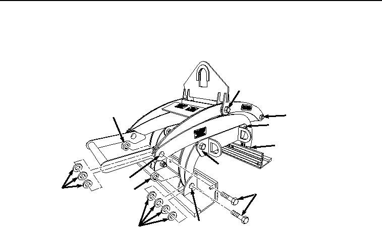
PIVOT BOLT SERVICE - Continued
1.
Remove locknut (Figure 1, Item 1), bolt (Figure 1, Item 2), and four washers (Figure 1, Item 3) from location
(Figure 1, Item 4). Discard locknut.
8
1
6
9
10
7
5
3
1
2
4
3
HYEX02155
Figure 1. Grapple Lubrication Locations.
2.
Clean and apply grease to bolt (Figure 1, Item 2).
3.
Install bolt (Figure 1, Item 2), four washers (Figure 1, Item 3), and locknut (Figure 1, Item 1) to location (Figure
1, Item 4).
4.
Remove locknut (Figure 1, Item 1), bolt (Figure 1, Item 2), and three washers (Figure 1, Item 3) from location
(Figure 1, Item 5). Discard locknut.
5.
Clean and apply grease to bolt (Figure 1, Item 2).
6.
Install bolt (Figure 1, Item 2), three washers (Figure 1, Item 3), and locknut (Figure 1, Item 1) to location (Figure
1, Item 5).
7.
Remove locknut (Figure 1, Item 1), bolt (Figure 1, Item 2), and two washers (Figure 1, Item 3) from location
(Figure 1, Item 6). Discard locknut.
8.
Clean and apply grease to bolt (Figure 1, Item 2).
9.
Install bolt (Figure 1, Item 2), two washers (Figure 1, Item 3), and locknut (Figure 1, Item 1) to location (Figure
1, Item 6).
10.
Repeat Steps (1) through (9) for remaining pivot point locations (Figure 1, Items 7, 8, 9, and 10) through (Figure
1, Item 10).
END OF TASK