
TM 5-3805-294-23-4
0646
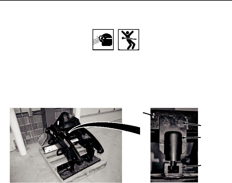
ACTUATOR SERVICE
WARNING
Safety glasses must be worn when using hammer and chisel. Material can be broken off and
act as projectiles. Failure to comply may result in serious injury or death to personnel.
NOTE
Actuator is welded to frame at factory for assembly. If actuator is being serviced for the first
time, welds must be broken. Actuator does not need to be welded to frame after replacement.
1.
Remove two screws (Figure 2, Item 11), lockwashers (Figure 2, Item 12), and nuts (Figure 2, Item 13) from
actuator assembly (Figure 2, Item 14) and upper arm assembly (Figure 2, Item 15). Discard lockwashers.
15
11, 12, 13
14
16
HYEX02904
Figure 2.
Barrier Grapple Actuator Removal.
2.
Remove actuator assembly (Figure 2, Item 14) from receiver block (Figure 2, Item 16).
3.
Clean and lubricate actuator assembly (Figure 2, Item 14) with rag and light weight oil.
4.
Check actuator assembly (Figure 2, Item 14) for signs of wear. Replace if necessary.
5.
Position actuator assembly (Figure 3, Item 14) in receiver block (Figure 3, Item 16).