
TM 5-3805-294-23-4
0645
REMOVAL - Continued
3.
Remove grapple pad (Figure 1, Item 1) from pad angle (Figure 1, Item 5).
END OF TASK
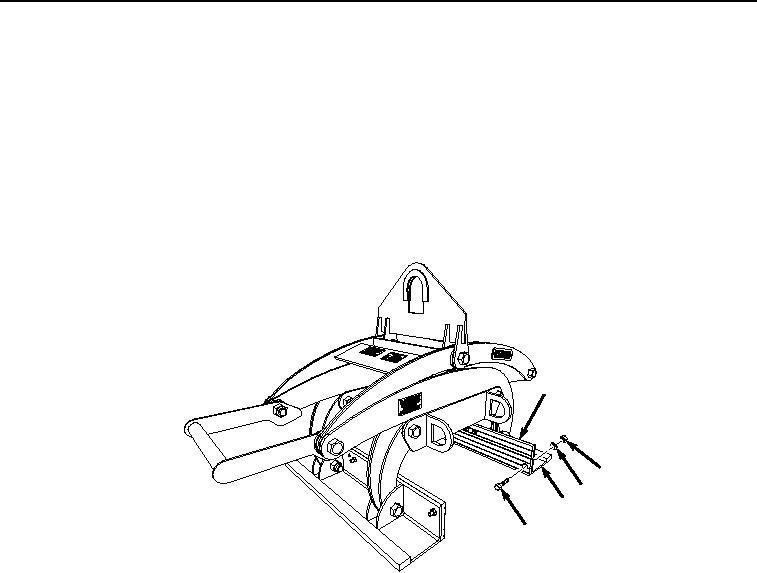
INSTALLATION
NOTE
There are two pads on the grapple assembly. Both pads are installed the same way.
1.
Position grapple pad (Figure 2, Item 1) on pad angle (Figure 2, Item 5).
1
2
3
5
4
HYEX01793
Figure 2. Barrier Grapple Pads Installation.
2.
Install grapple pad (Figure 2, Item 1) on pad angle (Figure 2, Item 5) with six bolts (Figure 2, Item 4),
lockwashers (Figure 2, Item 3), and nuts (Figure 2, Item 2).
END OF TASK
FOLLOW-ON MAINTENANCE
Perform the Standard Follow-On Maintenance Instructions. (Volume 3, WP 0384)
END OF TASK
END OF WORK PACKAGE