
TM 5-3805-294-23-4
FIELD MAINTENANCE
BARRIER GRAPPLE PADS REPLACEMENT
INITIAL SETUP:
Tools and Special Tools
References
Tool Kit, General Mechanic's: Automotive
TM 5-3805-294-24P: Fig. 146 (Volume 5,
(Volume 5, WP 0796, Table 2, Item 119)
WP 0794)
DA FORM 5988-E or DA FORM 2404 (Volume 5,
WP 0794)
Materials/Parts
Lockwasher
(Volume 5, WP 0798, Table 1, Item 144)
Time to Complete
Qty: 12
0.4 Hour(s)
Personnel Required
Construction Equipment Repairer 91L (1)
REMOVAL
NOTE
There are two pads on the grapple assembly. Both pads are removed the same way.
1.
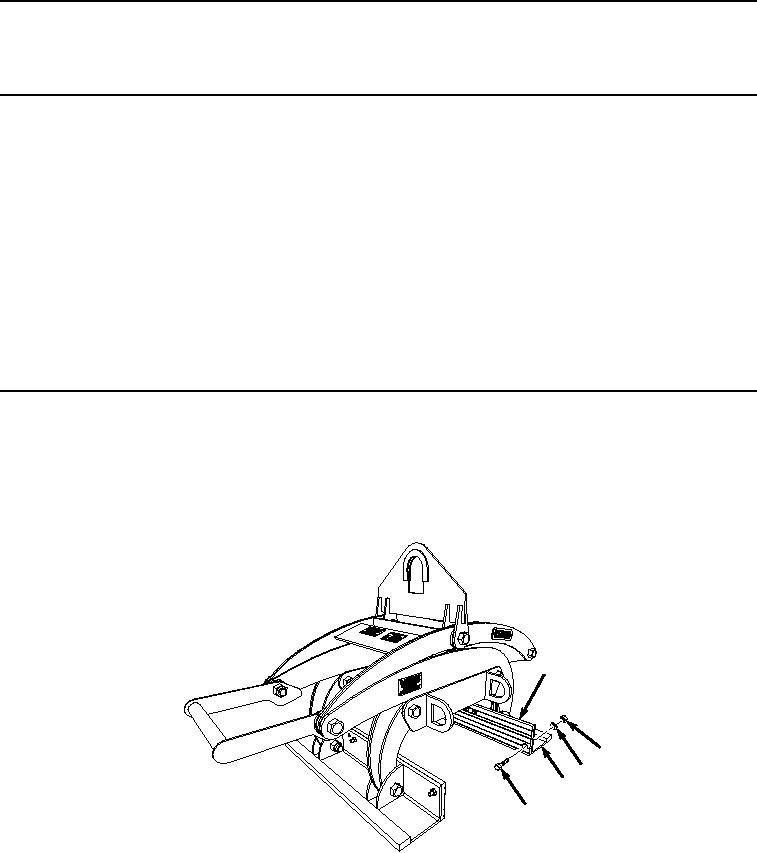
Place grapple assembly on the ground to allow access to grapple pad (Figure 1, Item 1) being removed.
1
2
3
5
4
HYEX01793
Figure 1. Barrier Grapple Pads Removal.
2.
Remove six nuts (Figure 1, Item 2), lockwashers (Figure 1, Item 3), and bolts (Figure 1, Item 4) from grapple
pad (Figure 1, Item 1) and pad angle (Figure 1, Item 5). Discard lockwashers.