
TM 5-3805-294-23-4
FIELD MAINTENANCE
BARRIER GRAPPLE PAD ANGLES REPLACEMENT
INITIAL SETUP:
Personnel Required
Tools and Special Tools
Construction Equipment Repairer 91L (2)
Tool Kit, General Mechanic's: Automotive
(Volume 5, WP 0796, Table 2, Item 119)
Handle, 3/4" Drive, 19 1/4" OAL (Volume 5,
References
WP 0796, Table 2, Item 55)
TM 5-3805-294-24P: Fig. 146 (Volume 5,
Lifting Device, Minimum Capacity 1000 lb
WP 0794)
Socket, Socket Wrench, 1-13/16 in., 3/4 in. Drive
DA FORM 5988-E or DA FORM 2404 (Volume 5,
(Volume 5, WP 0796, Table 2, Item 55)
WP 0794)
Wrench, Open End, Standard Length, 1-13/16 in.
(Volume 5, WP 0796, Table 2, Item 55)
Equipment Condition
Barrier grapple pads removed. (WP 0645)
Materials/Parts
Grease, Automotive and Artillery
(Volume 5, WP 0797, Table 1, Item 11)
Time to Complete
Locknuts (Volume 5, WP 0798, Table 1, Item
0.9 Hour(s)
143) Qty: 4
REMOVAL
NOTE
Both pad angles are removed in the same way. Both pad angles may be replaced at the
same time.
Note position of washers prior to removal of screws.
1.
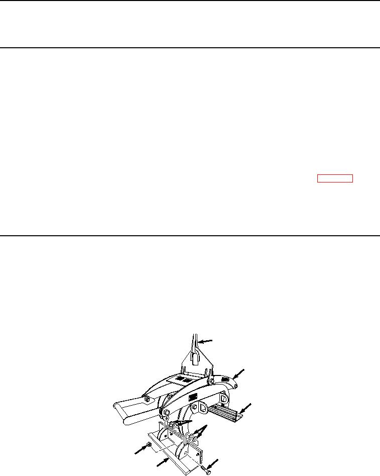
Connect suitable lifting device (Figure 1, Item 1) to barrier grapple (Figure 1, Item 2).
1
2
7
6
6
4
5
3
HYEX01799
Figure 1. Barrier Grapple Pad Angles Removal.