
TM 5-3805-294-23-4
0647
REMOVAL - Continued
NOTE
Position drain pan under hoses being removed.
Tag and mark hoses, fittings, and shims prior to removal to ensure proper installation.
19.
Remove boom load holding valve. (WP 0649)
20.
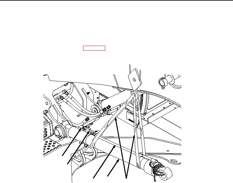
Remove hose (Figure 6, Item 17) from line (Figure 6, Item 18).
17
19
3
18
4
HYEX03468
Figure 6. Boom Cylinder Lower Pin Removal.
21.
Remove O-ring (Figure 6, Item 19) from line (Figure 6, Item 18). Discard O-ring.
22.
With the aid of an assistant and suitable lifting device (Figure 6, Item 4), lower boom cylinder (Figure 6, Item
3) to ground.
23.
Remove suitable lifting device (Figure 6, Item 4) from boom cylinder (Figure 6, Item 3).
24.
Re-attach suitable lifting device (Figure 6, Item 4) to boom cylinder (Figure 6, Item 3) with two points of lift at
each end of cylinder barrel.
25.
Raise boom cylinder (Figure 6, Item 3) to a level, horizontal position.
26.
Remove two nuts (Figure 7, Item 20) and bolt (Figure 7, Item 21) from machine (Figure 7, Item 22) and pin
(Figure 7, Item 23).