
TM 5-3805-294-23-4
0647
INSTALLATION - Continued
14.
Install pin (Figure 10, Item 23) to machine (Figure 10, Item 22) and boom cylinder (Figure 10, Item 3).
15.
Install bolt (Figure 10, Item 21) and two nuts (Figure 10, Item 20) to machine (Figure 10, Item 22) and pin
(Figure 10, Item 23).
NOTE
Screw should spin freely after two nuts have been tightened against each other.
16.
Tighten two nuts (Figure 10, Item 20) against each other to 405 lb-ft (549 Nm).
17.
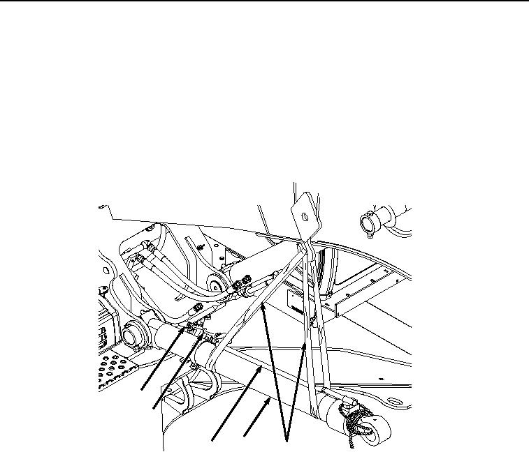
Lightly lubricate O-ring (Figure 11, Item 19) with clean oil.
17
19
3
18
4
HYEX03468
Figure 11. Hose Installation.
18.
Install O-ring (Figure 11, Item 19) to line (Figure 11, Item 18).
19.
Install hose (Figure 11, Item 17) to line (Figure 11, Item 18).
20.
With the aid of an assistant and suitable lifting device (Figure 11, Item 4), lower boom cylinder (Figure 11, Item
3) to ground.
21.
Remove suitable lifting device (Figure 11, Item 4) from boom cylinder (Figure 11, Item 3).
22.
Re-attach suitable lifting device (Figure 12, Item 4) to boom cylinder (Figure 12, Item 3) with a single point on
boom cylinder (Figure 12, Item 3) at rod (Figure 12, Item 14) end of boom cylinder barrel (Figure 12, Item 15).