
TM 5-3805-294-23-4
0647
INSTALLATION - Continued
14
3
4
15
16
HYEX03469
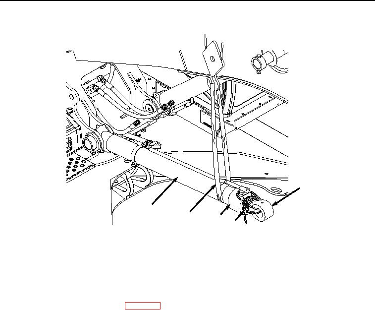
Figure 12. Lower Boom Cylinder.
23.
With the aid of an assistant and suitable lifting device (Figure 12, Item 4), raise boom cylinder (Figure 12, Item
3) until it is horizontal.
24.
Remove twine (Figure 12, Item 16) from cylinder rod (Figure 12, Item 14) and cylinder barrel (Figure 12, Item
15).
25.
Install boom load holding valve. (WP 0649)
26.
Start engine (TM 5-3805-294-10).
27.
Bleed boom cylinder. (Volume 5, WP 0696)
28.
With the aid of an assistant and suitable lifting device (Figure 13, Item 4), raise boom cylinder (Figure 13, Item
3).