
TM 5-3805-294-23-4
0647
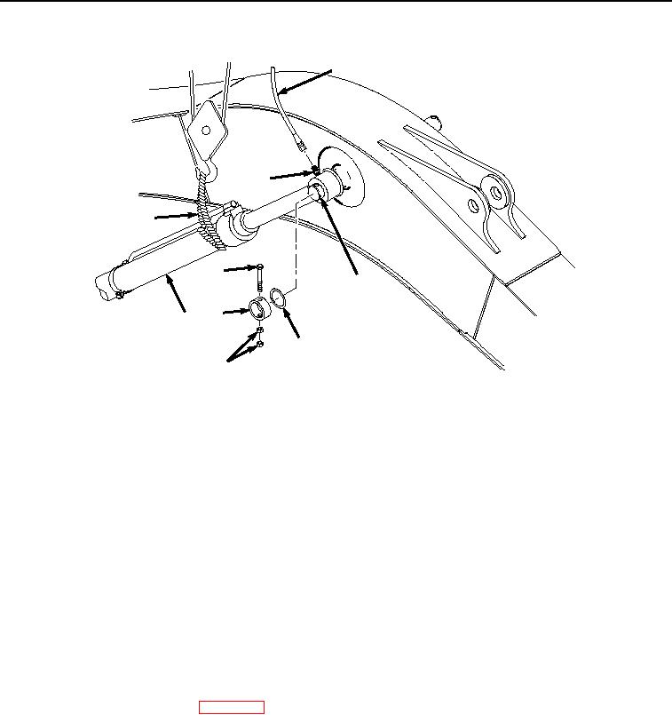
INSTALLATION - Continued
5
6
4
8
10
9
3
12
7
HYEX03474
Figure 14.
Sleeve Installation.
34.
Install sleeve (Figure 14, Item 9) to pin (Figure 14, Item 10) with bolt (Figure 14, Item 8), and two nuts (Figure
14, Item 7).
NOTE
Screw should spin freely after two nuts have been tightened against each other.
35.
Tighten two nuts (Figure 14, Item 7) against each other to 405 lb-ft (549 Nm).
36.
Install hose (Figure 14, Item 5) to fitting (Figure 14, Item 6).
37.
Remove suitable lifting device (Figure 14, Item 4) from boom cylinder (Figure 14, Item 3).
END OF TASK
FOLLOW-ON MAINTENANCE
1.
Install boom cylinder guard. (WP 0648)
2.
Perform the Standard Follow-On Maintenance Instructions. (Volume 3, WP 0384)
END OF TASK
END OF WORK PACKAGE