
TM 5-3805-294-23-4
0647
INSTALLATION - Continued
WARNING
ADHESIVES AND SEALANTS
NOTE
Install hoses, fittings, and shims as noted prior to removal.
Remove caps and plugs as hoses and fittings are installed.
Left and right side boom cylinders are installed the same way. Right side boom cylinder
shown.
1.
Apply pipe thread sealing compound to threads of fitting (Figure 9, Item 33).
25
18
6
26
14
27
27
3
16
29
30
15
31
30
28
32
33
28
HYEX00781
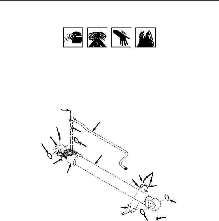
Figure 9.
Boom Cylinder Hardware Installation.
2.
Install fitting (Figure 9, Item 33) to boom cylinder (Figure 9, Item 3).
3.
Install clamp (Figure 9, Item 32) and clamp (Figure 9, Item 31) to boom cylinder (Figure 9, Item 3) with two
lockwashers (Figure 9, Item 30) and bolts (Figure 9, Item 29).
4.
Install two seals (Figure 9, Item 28) to boom cylinder (Figure 9, Item 3).
5.
Install two seals (Figure 9, Item 27) to boom cylinder (Figure 9, Item 3).
6.
Lightly lubricate O-ring (Figure 9, Item 26) with clean oil.