
TM 5-3805-294-23-4
0647
REMOVAL
25
18
6
26
14
27
27
3
16
29
30
15
31
30
28
32
33
28
HYEX00781
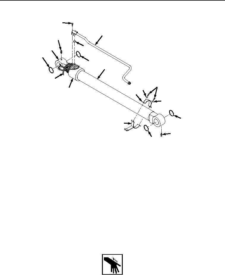
Figure 8. Boom Cylinder Hardware Removal.
32.
Remove four screws (Figure 8, Item 25) from line (Figure 8, Item 18) and boom cylinder (Figure 8, Item 3).
33.
Remove line (Figure 8, Item 18) and O-ring (Figure 8, Item 26) from boom cylinder (Figure 8, Item 3). Discard
O-ring.
34.
Remove two seals (Figure 8, Item 27) from boom cylinder (Figure 8, Item 3). Discard seals.
35.
Remove two seals (Figure 8, Item 28) from boom cylinder (Figure 8, Item 3). Discard seals.
36.
Remove two bolts (Figure 8, Item 29), lockwashers (Figure 8, Item 30), clamp (Figure 8, Item 31), and clamp
(Figure 8, Item 32) from boom cylinder (Figure 8, Item 3). Discard lockwashers.
37.
Remove fitting (Figure 8, Item 33) from boom cylinder (Figure 8, Item 3).
38.
Remove twine (Figure 8, Item 16) from cylinder rod (Figure 8, Item 14) and cylinder barrel (Figure 8, Item 15).
END OF TASK
INSTALLATION
WARNING