
TM 5-2420-230-24-1
a. Removal.
NOTE
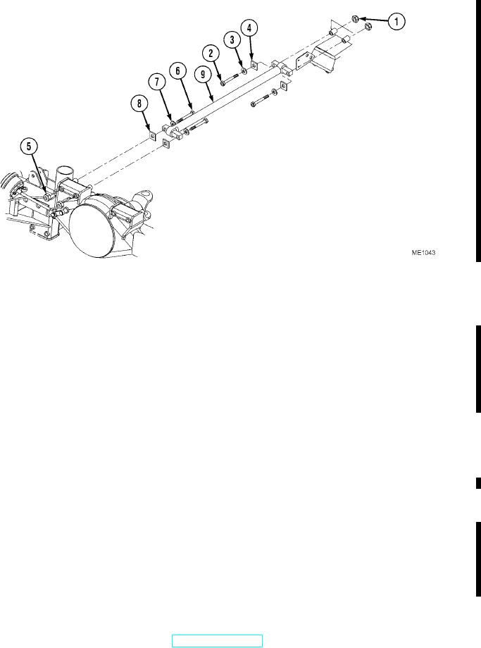
All control arms are removed in the same manner. The front control arms are shown.
(1)
Remove two self-locking nuts (1), bolts (2), washers (3), and shims (4). Discard self-locking nuts.
(2)
Remove two self-locking nuts (5), bolts (6), washers (7), shims (8), and control arm (9). Discard self-locking nuts.
(3)
Deleted.
b. Installation.
NOTE
All control arms are installed in the same manner. The front control arms are shown.
Add shims as required.
(1)
Install shims (8), two bolts (6), washers (7), and new self-locking nuts (5). Tighten bolts to 94 lbf/ft (128 Nm).
(2)
Install control arm (9) with shims (4), two bolts (2), washers (3), and new self-locking nuts (1). Tighten bolts to
94 lbf/ft (128 Nm).
(3)
Deleted.
c. Follow-On Maintenance.
Remove "Do Not Operate" tag from ignition switch (TM 5-2420-230-10).
END OF TASK
Change 1
6-13