
TM 5-2420-230-24-1
6-10. SWAY BAR REPLACEMENT.
This Task Covers:
a. Removal
b. Inspection
c. Installation
d. Follow-On Maintenance
INITIAL SETUP
Test Equipment
Equipment Conditions
None
TM or Para
Condition Description
Vehicle positioned on level
ground.
Tools and Special Tools
Tool kit, common no. 2, Item 36, Appendix B
Parking brake applied.
Tool kit, general mechanics, Item 38, Appendix B
Engine shut OFF.
Electrical master switch OFF.
"Do Not Operate" tag attached
Material/Parts
Nut, self-locking, Item 123, Appendix D (4)
to ignition switch.
Nut, self-locking, Item 125, Appendix D (4)
Washer, lock, Item 282, Appendix D (4)
Drawings Required
TM 5-2420-230-24P Figure 119
Personnel Required
MOS 62B, Construction Equipment Repairer (2)
Estimated Time to Complete
Refer to MAC in Appendix B
References
None
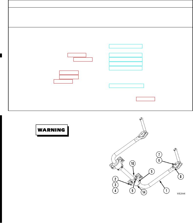
a. Removal.
The sway bar is heavy and it is under tension
when installed. To prevent injury, take care when
removing and installing sway bar. Failure to
comply may result in injury or death to
personnel.
(1)
Place jack under center of sway bar (1) and raise
jack to support weight of sway bar.
(2)
Remove four bolts (2), washers (3),
lockwashers (4), and two sway bar supports (5)
from vehicle. Discard lockwashers.
(3)
Carefully lower jack.
(4)
Support sway bar (1) and remove four bolts (6) and self-locking nuts (7) from connecting arms (8). Discard self-
locking nuts.
(5)
Remove four screws (9) from two split collars (10), and remove split collars from sway bar (1).
Change 1