
TM 5-2420-230-24-1
c. Adjustment.
(1)
Start engine (TM 5-2420-230-10).
(2)
Ensure air system is full and vehicle is parked
on level ground.
(3)
Shut OFF engine (TM 5-2420-230-10).
(4)
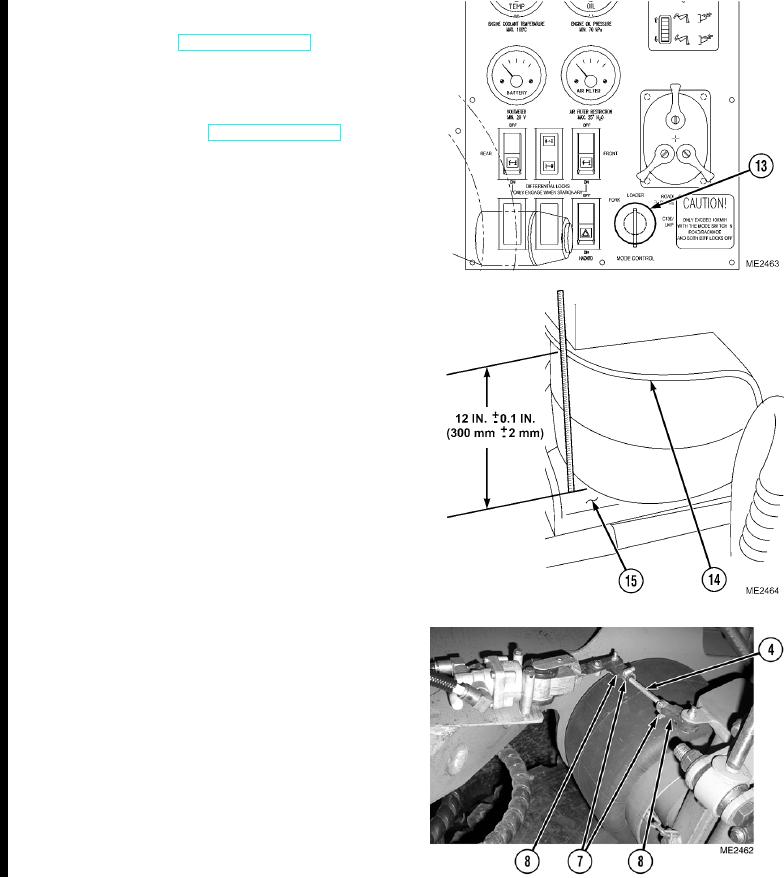
Set suspension MODE CONTROL switch (13)
to ROAD/BACKHOE mode.
(5)
Check ride height by measuring distance
between top (14) and bottom (15) air bag
mounting plate on airbags.
NOTE
Average height is 12 0.1 in. (300 2 mm). It
is important that the vehicle remains level. The
variation in airbag dimension allows for
manufacturing tolerances.
(6)
Loosen clamps (7), adjust rod ends (8) on
linkage (4) to obtain the proper ride height.
Tighten clamps.
(7)
Test drive vehicle over rough surfaces, bumps,
or gutters to ensure proper suspension
movement. Upon completion of test drive,
perform Steps (8) through (10).
(8)
Park vehicle on level ground.
(9)
Ensure air pressure is at maximum pressure.
(10) Visually inspect vehicle from approximately
30 ft. (10m) to ensure it looks level in relation
to the ground.
END OF TASK
Change 1
6-10