
TM 5-2420-230-24-1
6-7. RIDE LEVEL VALVE (RLV) AND LINKAGE REPLACEMENT.
This Task Covers:
a. Removal
b. Installation
c. Adjustment
INITIAL SETUP
Test Equipment
References
None
None
Tools and Special Tools
Equipment Conditions
Tool kit, common no. 2, Item 36, Appendix B
TM or Para
Condition Description
Tool kit, general mechanics, Item 38, Appendix B
Air system drained.
Materials/Parts
Drawings Required
Cap and plug set, Item 4, Appendix C
TM 5-2420-230-24P Figure 117
Tags, identification, Item 63, Appendix C
Ties, cable, Item 68, Appendix C
Estimated Time to Complete
Refer to MAC in Appendix B
Personnel Required
MOS 62B, Construction Equipment Repairer
a. Removal.
NOTE
Tag all hoses, wires, and tubes and note their positions before removal.
Remove cable ties as necessary.
Cap and plug all tubes, hoses, and fittings upon removal.
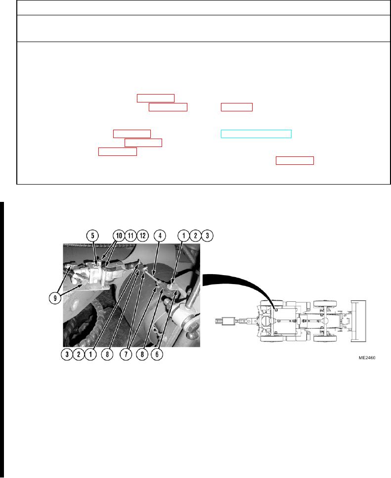
Front and rear valves and linkages are removed in a similar manner. Rear shown.
If only replacing linkage, just perform Steps (1) and (2). Remaining steps apply only if replacing
entire RLV.
Change 1