
TM 5-2420-230-24-1
6-8. SHOCK ABSORBER MAINTENANCE.
This Task Covers:
a. Removal
b. Disassembly
c. Assembly
d. Installation
e. Follow-On Maintenance
INITIAL SETUP
Test Equipment
References
None
None
Equipment Conditions
Tools and Special Tools
TM or Para
Condition Description
Tool kit, common no. 2, Item 36, Appendix B
Vehicle raised.
Tool kit, general mechanics, Item 38, Appendix B
Tire assembly removed.
Materials/Parts
Drawings Required
Bushing, shock, Item 36, Appendix D (4)
TM 5-2420-230-24P Figure 114
Nut, self-locking, Item 123, Appendix D (2)
Estimated Time to Complete Task
Refer to MAC in Appendix B
Personnel Required
MOS 62B, Construction Equipment Repairer
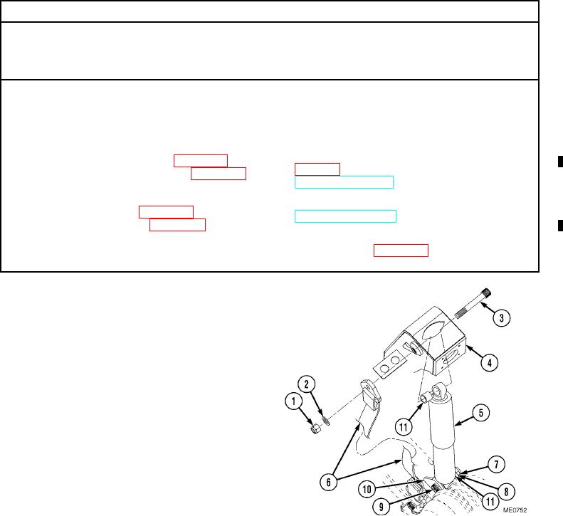
a. Removal.
(1)
Remove self-locking nut (1), washer (2), and
mounting bolt (3) from mount (4) at top of
shock absorber (5). Discard self-locking nut.
(2)
Lay check strap (6) to the side.
(3)
Remove self-locking nut (7), washer (8), and
mounting bolt (9) from mount (10) at
bottom of shock absorber (5). Discard
self-locking nut.
(4)
Remove shock absorber (5).
b. Disassembly.
Remove two bushings (11) from top and bottom of
shock absorber (5).
c. Assembly.
Install two bushings (11) into top and bottom of shock absorber (5).
d. Installation.
(1)
Install shock absorber (5) in bottom mount (10) with mounting bolt (9), washer (8), and new self-locking nut (7).
(2)
Install shock absorber (5) and check strap (6) to top mount (4) with mounting bolt (3), washer (2), and one new
self-locking nut (1).
(3)
Tighten mounting bolts (3) and (9) to 98 lbf/ft (133 Nm).
Change 1