
TM 5-2420-230-24-1
NOTE
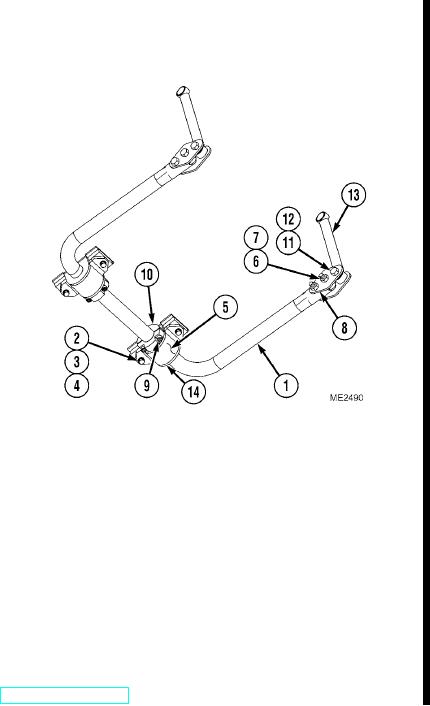
If tie rod bar requires replacement, record length of old tie-rod for new installation.
(6)
If required, remove four self-locking nuts (11),
bolts (12), connecting arms (8), and two tie rod
bars (13) from vehicle. Discard self-locking nuts.
b. Inspection.
Visually inspect sway bar (1), sway bar supports (5),
connecting arms (8), and bushings (14) for damage,
distortion, and/or cracks. Replace components as
necessary.
c. Installation.
NOTE
Ensure sway bar is aligned equally.
(1)
If removed, install tie-rod bar (13) and
connecting arms (8) on vehicle with four
bolts (12) and new self-locking nuts (11). Torque self-locking nuts to 375 lbf/ft (508 Nm).
(2)
Place jack under center of sway bar (1), and raise jack to support weight of sway bar.
(3)
Install sway bar supports (5) on vehicle with four washers (4), new lockwashers (3), and bolts (2).
(4)
Carefully lower jack.
(5)
Position split collars (10) on sway bar (1) and secure with four screws (9).
(6)
Install sway bar (1) with four bolts (6) and new self-locking nuts (7). Torque self-locking nuts to 210 lbf/ft
(285 Nm).
d. Follow-On Maintenance.
Remove "Do Not Operate" tag from ignition switch (TM 5-2420-230-10).
END OF TASK
Change 1
6-15/6-16 blank