
TM 5-3805-294-23-4
0511
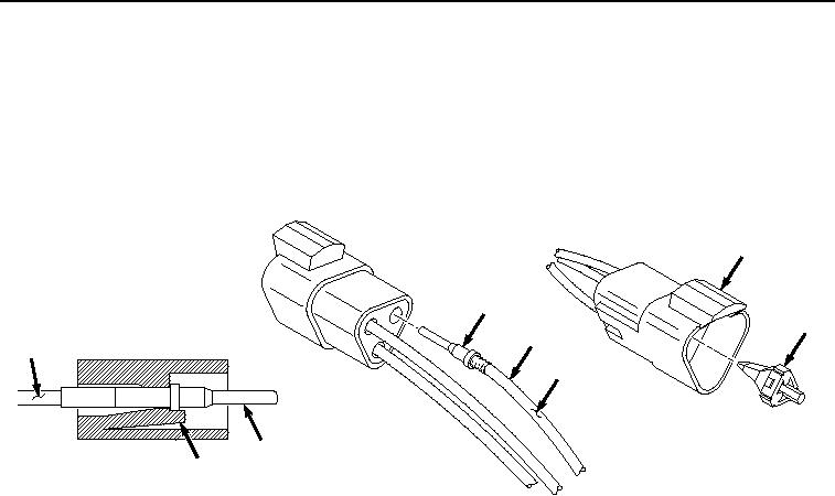
DEUTSCH DT STYLE CONNECTOR RECEPTACLE REPAIR - Continued
NOTE
Tag and mark wires, connectors, and wiring harnesses prior to removal to ensure proper
installation.
Note position of each tie wrap and remove as required.
1.
Remove wedge lock (Figure 3, Item 7) from connector (Figure 3, Item 8).
8
10
7
12
11
11
10
9
HYEX03217
Figure 3. DT Style Connector Receptacle Repair.
NOTE
Hold rear grommet when pulling terminal and wire out, to prevent displacing rear grommet.
2.
Move locking finger (Figure 3, Item 9) away from terminal (Figure 3, Item 10) while gently pulling wire (Figure
3, Item 11) out the back side of connector (Figure 3, Item 8).
3.
Cut and remove terminal (Figure 3, Item 10) from wire (Figure 3, Item 11).
4.
Remove 1/4 in. (6 mm) of insulation (Figure 3, Item 12) from end of wire (Figure 3, Item 11).
NOTE
Ensure all strands of wire are inside terminal when installing.
5.
Install wire (Figure 3, Item 11) to terminal (Figure 3, Item 10) and crimp.
6.
Insert terminal (Figure 3, Item 10) and wire (Figure 3, Item 11) into connector (Figure 3, Item 8) and push until
terminal (Figure 3, Item 10) stops.
7.
Pull on wire (Figure 3, Item 11) to confirm that terminal (Figure 3, Item 10) is locked in connector (Figure 3,
Item 8).
8.
Install wedge lock (Figure 3, Item 7) into connector (Figure 3, Item 8) until it snaps into place.
END OF TASK