
TM 5-3805-294-23-4
0524
INSTALLATION - Continued
6
5
9
8
3
7
12 11 10 1 2 4
HYEX01928
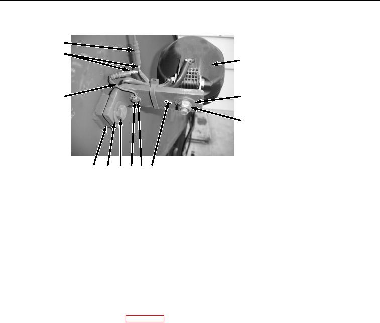
Figure 4. Right Boom Work Light and Harness Installation.
4.
Install right boom work light (Figure 4, Item 9) to angle mounting bracket (Figure 4, Item 4) with washer (Figure
4, Item 8) and locknut (Figure 4, Item 7).
5.
Connect right boom work light wire (Figure 4, Item 5) to wire harness E4 (Figure 4, Item 6).
6.
Connect right boom work light wire (Figure 4, Item 5) to wire harness (Figure 4, Item 3).
7.
Install ring end of wire harness (Figure 4, Item 3) to angle mounting bracket (Figure 4, Item 4) with washer
(Figure 4, Item 2) and bolt (Figure 4, Item 1).
END OF TASK
FOLLOW-ON MAINTENANCE
1.
Connect negative battery cable. (WP 0521)
2.
Perform the Standard Follow-On Maintenance Instructions. (Volume 3, WP 0384)
END OF TASK
END OF WORK PACKAGE