
TM 5-3805-294-23-4
0525
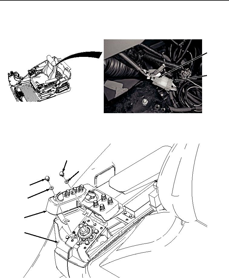
REMOVAL - Continued
1.
Remove right-hand console wire harness connector (Figure 1, Item 1) from switch panel connector (Figure 1,
Item 2).
2
1
HYEX03352
Figure 1. Disconnect Switch Panel.
2.
Remove two screws (Figure 2, Item 3), washers (Figure 2, Item 4), and switch panel (Figure 2, Item 5) from
right-hand console (Figure 2, Item 6).
3
4
3
4
5
6
HYEX03353
Figure 2. Right-Hand Switch Panel Removal.
3.
Remove right-hand console wiring harness connector (Figure 3, Item 7) from key switch (Figure 3, Item 8).