
TM 5-3805-294-23-4
0525
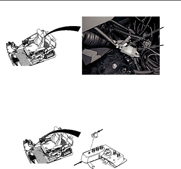
INSTALLATION - Continued
2
1
HYEX03352
Figure 8. Connect Switch Panel.
END OF TASK
KNOB REMOVAL
NOTE
There are six knobs on the switch panel. They are all removed the same way.
Remove knob (Figure 9, Item 14) from switch panel (Figure 9, Item 5).
14
5
HYEX00892
Figure 9.
Dial Knob Removal.
END OF TASK
KNOB INSTALLATION
NOTE
There are six knobs on the switch panel. They are all installed the same way.
Install knob (Figure 10, Item 14) to switch panel (Figure 10, Item 5).