
TM 5-3805-294-23-4
0526
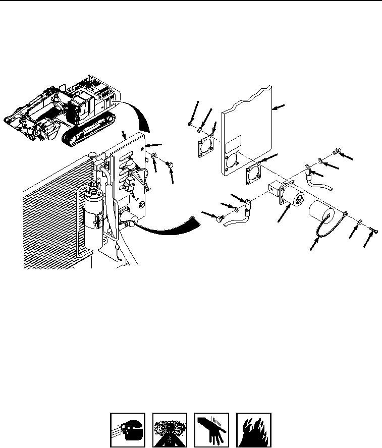
INSTALLATION - Continued
tools can catch on equipment, contact positive electrical circuits, and cause a direct short,
severe burns, or electrical shock. Failure to comply may result in injury or death to personnel.
1.
Install backing plate (Figure 2, Item 18) and slave receptacle (Figure 2, Item 5) to bracket (Figure 2, Item 3).
12
13
3
14
4
S
LT
VO VE
3
24 SLA LE
C TAC
D P
E
EC
18
R
8
9
2
6
1
7
S
11
LT
VO VE
24 SLA LE
C
DC PTA
CE
10
RE
5
16
15
17
HYEX01178
Figure 2.
Slave Receptacle Installation.
2.
Install dust cover (Figure 2, Item 17), four washers (Figure 2, Item 16), and bolts (Figure 2, Item 15) to slave
receptacle (Figure 2, Item 5) and bracket (Figure 2, Item 3).
3.
Install backing plate (Figure 2, Item 14) to bracket (Figure 2, Item 3) and bolts (Figure 2, Item 15).
4.
Install four washers (Figure 2, Item 13) and locknuts (Figure 2, Item 12) to backing plate (Figure 2, Item 14)
and screws (Figure 2, Item 15).
5.
Install cable (Figure 2, Item 7) on slave receptacle (Figure 2, Item 5) with bolt (Figure 2, Item 10) and lockwasher
(Figure 2, Item 11).
6.
Install cable (Figure 2, Item 6) on slave receptacle (Figure 2, Item 5) with bolt (Figure 2, Item 8) and lockwasher
(Figure 2, Item 9).
WARNING
ADHESIVES AND SEALANTS
7.
Apply sealant to rear of slave receptacle (Figure 2, Item 5) and cables (Figure 2, Item 7 and 6), as necessary.