
TM 5-3805-294-23-4
0525
INSTALLATION
WARNING
Ensure electrical power is off prior to working on all electrical connections. Prior to working
on or around vehicle, remove all jewelry, such as rings, ID tags, bracelets, etc. Jewelry, and
tools can catch on equipment, contact positive electrical circuits, and cause a direct short,
severe burns, or electrical shock. Failure to comply may result in injury or death to personnel.
NOTE
Install wires, connectors, and wiring harnesses as noted prior to removal.
Install tie wraps as noted prior to removal.
1.
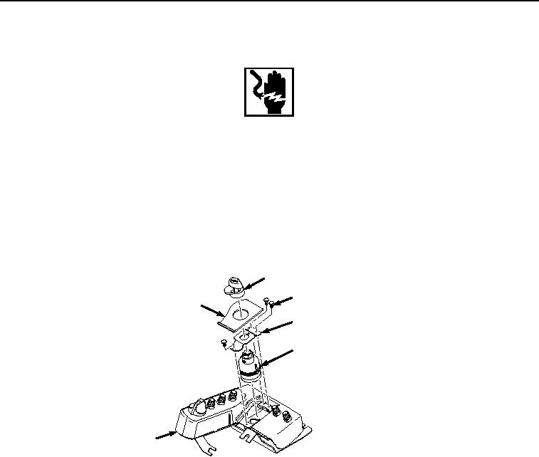
Install key switch (Figure 5, Item 8) to switch panel (Figure 5, Item 5).
10
12
11
13
8
5
HYEX00894
Figure 5. Key Switch Installation.
2.
Install bracket (Figure 5, Item 13) to switch panel (Figure 5, Item 5) with three screws (Figure 5, Item 12).
3.
Install key switch legend plate (Figure 5, Item 11) to switch panel (Figure 5, Item 5).
4.
Install key switch cover (Figure 5, Item 10) to switch panel (Figure 5, Item 5).
5.
Position switch panel (Figure 6, Item 5) in cab (Figure 6, Item 9).