
TM 5-3805-294-23-4
0525
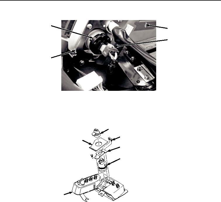
REMOVAL - Continued
8
9
7
5
HYEX03351
Figure 3.
Disconnect Key Switch.
4.
Remove switch panel (Figure 3, Item 5) from cab (Figure 3, Item 9).
5.
Remove key switch cover (Figure 4, Item 10) from switch panel (Figure 4, Item 5).
10
12
11
13
8
5
HYEX00894
Figure 4. Key Switch Removal.
6.
Remove key switch legend plate (Figure 4, Item 11) from switch panel (Figure 4, Item 5).
7.
Remove three screws (Figure 4, Item 12) and bracket (Figure 4, Item 13) from switch panel (Figure 4, Item 5).
8.
Remove key switch (Figure 4, Item 8) from switch panel (Figure 4, Item 5).
END OF TASK