• Home
  • Download PDF
  • Order CD-ROM
  • Order in Print
Figure 6. Seat Installation.
Figure 9. Cap and Cover Removal.

Maintenance Manual For Hydraulic Excavator Type 1 With Hydraulic Thumb And Quick Latch -4 Page Navigation
  684    685    686    687    688  689  690    691    692    693    694  
img
.
TM 5-3805-294-23-4
0580
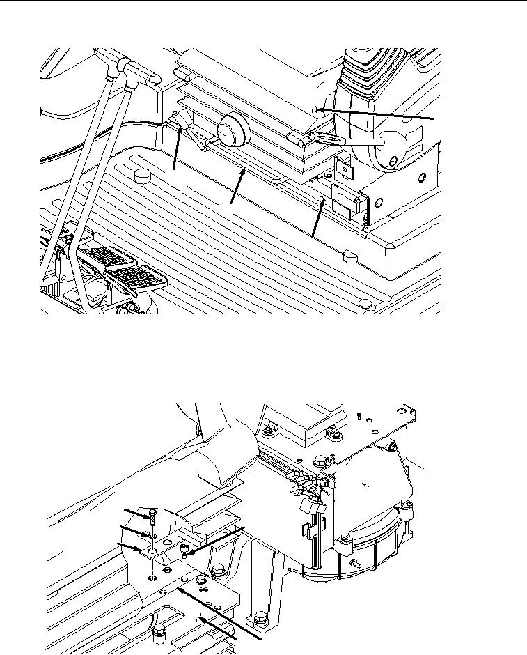
INSTALLATION - Continued
9
7
8
6
HYEX00833
Figure 7. Move Seat stand Forward.
4.
Pull lever (Figure 7, Item 8) up and move seat (Figure 7, Item 9) forward until it stops.
5.
Install two screws (Figure 8, Item 13) to seat rails (Figure 8, Item 14) and seat stand (Figure 8, Item 6).
10
13
11
12
6
14
HYEX00834
Figure 8. Seat Stop Installation.
0580-6


Privacy Statement
Press Release
Contact

© Copyright Integrated Publishing, Inc.. All Rights Reserved.