• Home
  • Download PDF
  • Order CD-ROM
  • Order in Print
Figure 1. Seat Stand Cover Removal
Figure 4. Right-Hand Console Removal.

Maintenance Manual For Hydraulic Excavator Type 1 With Hydraulic Thumb And Quick Latch -4 Page Navigation
  688    689    690    691    692  693  694    695    696    697    698  
img
.
TM 5-3805-294-23-4
0581
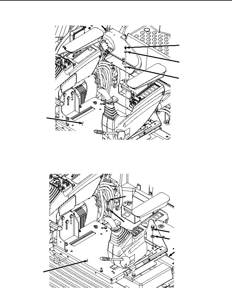
SEAT STAND REMOVAL - Continued
11
8
9
10
6
HYEX02029
Figure 2.
Heater Duct Removal.
5.
Remove two screws (Figure 3, Item 12) and washers (Figure 3, Item 13) from seat stand (Figure 3, Item 6)
and rear seat stand support (Figure 3, Item 14).
12
13
12
13
14
6
HYEX02030
Figure 3.
Seat Stand Screws Removal.
0581-3


Privacy Statement
Press Release
Contact

© Copyright Integrated Publishing, Inc.. All Rights Reserved.