Home
Download PDF
Order CD-ROM
Order in Print
Figure 4. Right-Hand Console Removal.
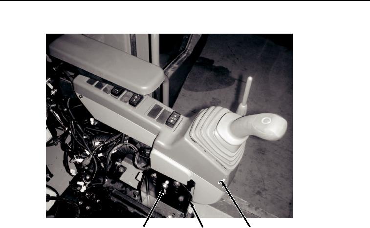
Figure 6. Seat Stand Removal.
Maintenance Manual For Hydraulic Excavator Type 1 With Hydraulic Thumb And Quick Latch -4
Page Navigation
690
691
692
693
694
695
696
697
698
699
700
TM
5-3805-294-23-4
0581
SEAT
STAND
REMOVAL
- Continued
18,
19
6
20
HYEX02032
Figure
5.
Left-Hand
Console
Removal.
8.
Push
lever
(Figure
6,
Item
7)
down
and
move
seat
stand
(Figure
6,
Item
6) backward.
0581-5