
TM 5-3805-294-23-4
0581
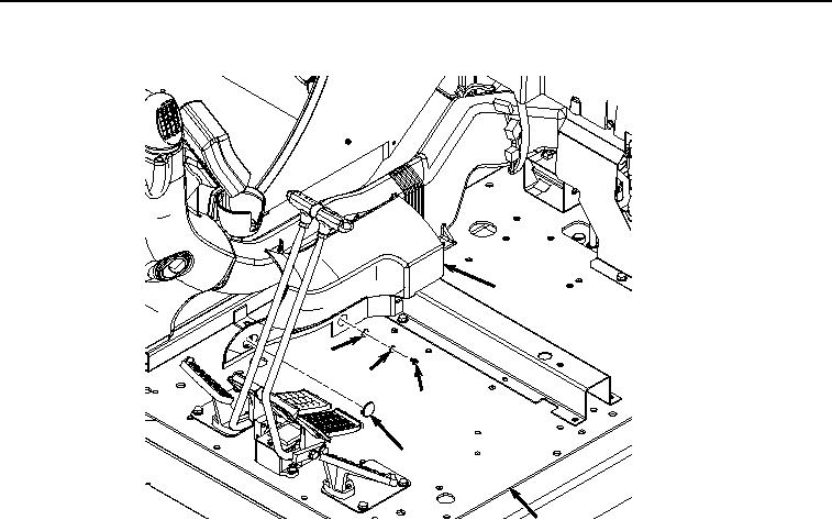
SUPPORTS REMOVAL - Continued
38
41
40
39
37
24
HYEX02037
Figure 10. Duct Cover Removal.
7.
Remove three screws (Figure 10, Item 39), lockwashers (Figure 10, Item 40), washers (Figure 10, Item 41),
and cover (Figure 10, Item 38) from cab (Figure 10, Item 24). Discard lockwashers.
8.
Remove bolt (Figure 11, Item 42), washer (Figure 11, Item 43), and duct (Figure 11, Item 44) from cab (Figure
11, Item 24).