• Home
  • Download PDF
  • Order CD-ROM
  • Order in Print
Figure 10. Duct Cover Removal.
Figure 12. Front Seat Stand Support Removal.

Maintenance Manual For Hydraulic Excavator Type 1 With Hydraulic Thumb And Quick Latch -4 Page Navigation
  695    696    697    698    699  700  701    702    703    704    705  
img
.
TM 5-3805-294-23-4
0581
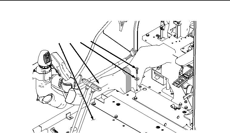
SUPPORTS REMOVAL - Continued
24
44
43
42
HYEX03535
Figure 11. Duct Removal.
9.
Remove six screws (Figure 12, Item 45), washers (Figure 12, Item 46), and front seat stand support (Figure
12, Item 23) from cab (Figure 12, Item 24).
0581-10


Privacy Statement
Press Release
Contact

© Copyright Integrated Publishing, Inc.. All Rights Reserved.