• Home
  • Download PDF
  • Order CD-ROM
  • Order in Print
Figure 6. Seat Stand Removal.
Figure 9. Rear Seat Stand Support Removal.

Maintenance Manual For Hydraulic Excavator Type 1 With Hydraulic Thumb And Quick Latch -4 Page Navigation
  692    693    694    695    696  697  698    699    700    701    702  
img
.
TM 5-3805-294-23-4
0581
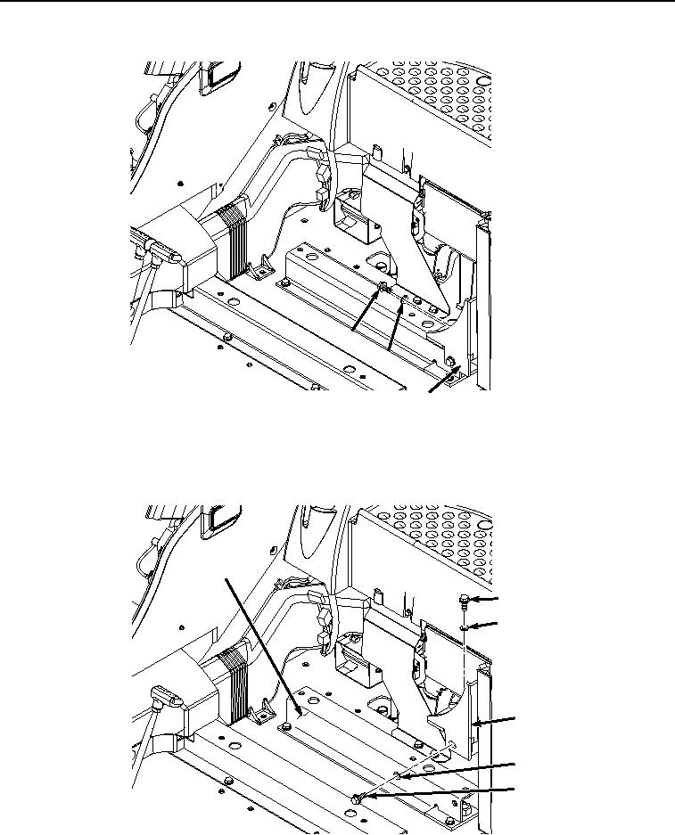
SUPPORTS REMOVAL - Continued
25
26
27
HYEX02034
Figure 7.
Bracket Screw Removal.
2.
Remove screw (Figure 8, Item 28) and washer (Figure 8, Item 29) from bracket (Figure 8, Item 27) and rear
seat stand support (Figure 8, Item 14).
14
30
31
27
29
28
HYEX02035
Figure 8. Bracket Removal.
0581-7


Privacy Statement
Press Release
Contact

© Copyright Integrated Publishing, Inc.. All Rights Reserved.