
TM 5-3805-294-23-4
0581
SUPPORTS REMOVAL - Continued
3.
Remove screw (Figure 8, Item 30), washer (Figure 8, Item 31), and bracket (Figure 8, Item 27) from rear seat
stand support (Figure 8, Item 14).
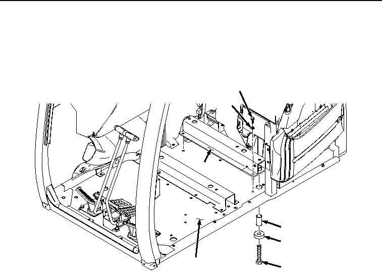
4.
Remove screw (Figure 9, Item 32), washer (Figure 9, Item 33), and spacer (Figure 9, Item 34) from rear seat
stand support (Figure 9, Item 14).
35
36
14
34
33
24
32
HYEX02036
Figure 9.
Rear Seat Stand Support Removal.
5.
Remove five screws (Figure 9, Item 35), washers (Figure 9, Item 36), and rear seat stand support (Figure 9,
Item 14) from cab (Figure 9, Item 24).
6.
Remove cap (Figure 10, Item 37) from cover (Figure 10, Item 38).