
TM 5-3805-294-23-4
0581
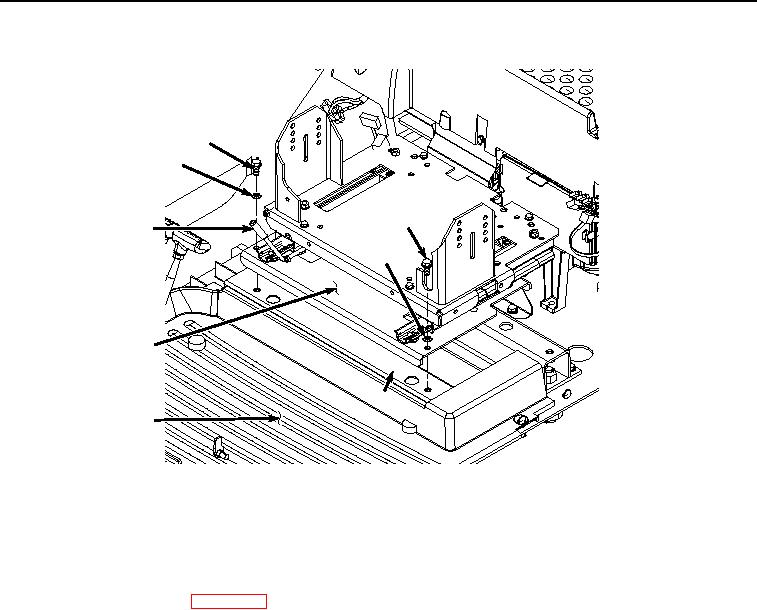
SEAT STAND REMOVAL
21
22
21
7
22
6
23
24
HYEX02033
Figure 6. Seat Stand Removal.
9.
Remove two screws (Figure 6, Item 21) and washers (Figure 6, Item 22) from seat stand (Figure 6, Item 6)
and front seat stand support (Figure 6, Item 23).
10.
Remove seat stand (Figure 6, Item 6) from cab (Figure 6, Item 24).
11.
Remove cab floor mat. (WP 0558)
END OF TASK
SUPPORTS REMOVAL
1.
Remove screw (Figure 7, Item 25) and washer (Figure 7, Item 26) from bracket (Figure 7, Item 27).