• Home
  • Download PDF
  • Order CD-ROM
  • Order in Print
Figure 11. Duct Removal.
Figure 13. Seat Stand Disassembly.

Maintenance Manual For Hydraulic Excavator Type 1 With Hydraulic Thumb And Quick Latch -4 Page Navigation
  696    697    698    699    700  701  702    703    704    705    706  
img
.
TM 5-3805-294-23-4
0581
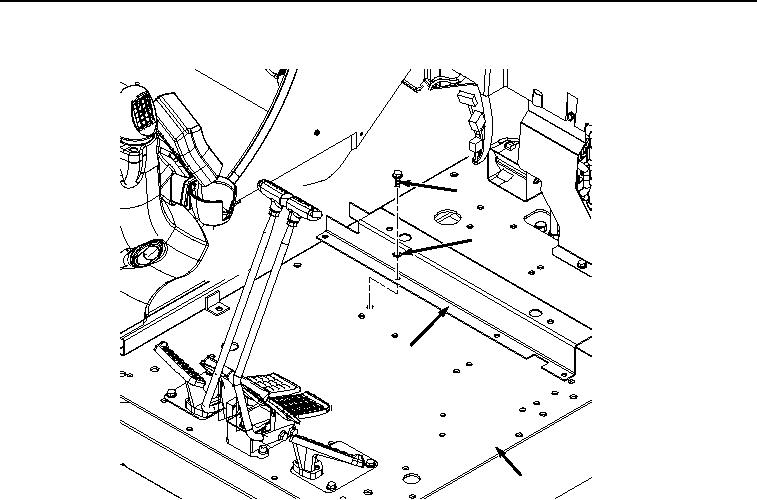
SUPPORTS REMOVAL - Continued
45
46
23
24
HYEX02038
Figure 12.
Front Seat Stand Support Removal.
END OF TASK
SEAT STAND DISASSEMBLY
1.
Remove four nuts (Figure 13, Item 47), lockwashers (Figure 13, Item 48), and base (Figure 13, Item 49) from
slide assembly (Figure 13, Item 50). Discard lockwashers.
0581-11


Privacy Statement
Press Release
Contact

© Copyright Integrated Publishing, Inc.. All Rights Reserved.