
TM 5-3805-294-23-4
0581
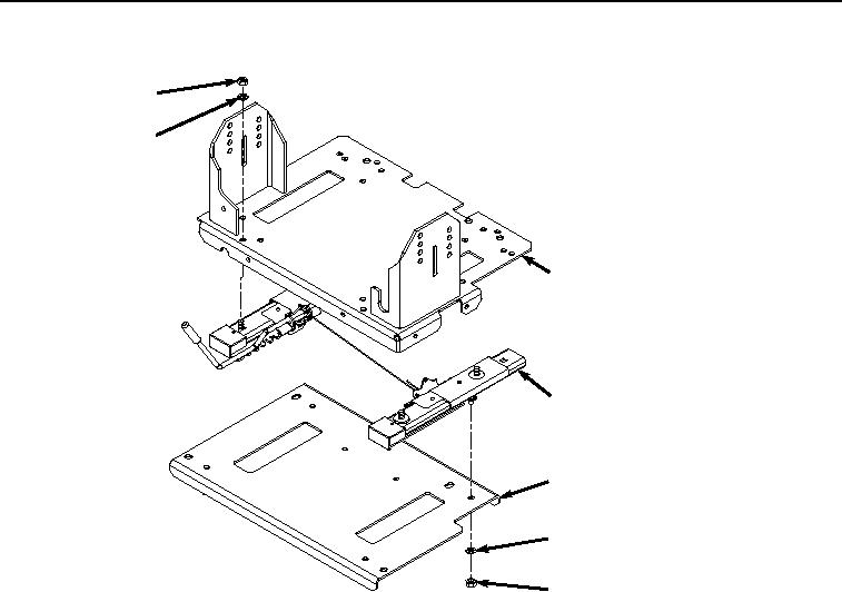
SEAT STAND DISASSEMBLY - Continued
47
48
49
50
53
52
51
HYEX02844
Figure 13.
Seat Stand Disassembly.
2.
Remove four nuts (Figure 13, Item 51), lockwashers (Figure 13, Item 52), and slide assembly (Figure 13, Item
50) from plate (Figure 13, Item 53). Discard lockwashers.
END OF TASK
SEAT STAND ASSEMBLY
1.
Install slide assembly (Figure 14, Item 50) to plate (Figure 14, Item 53) with four nuts (Figure 14, Item 51) and
lockwashers (Figure 14, Item 52).