
TM 5-3805-294-23-4
0581
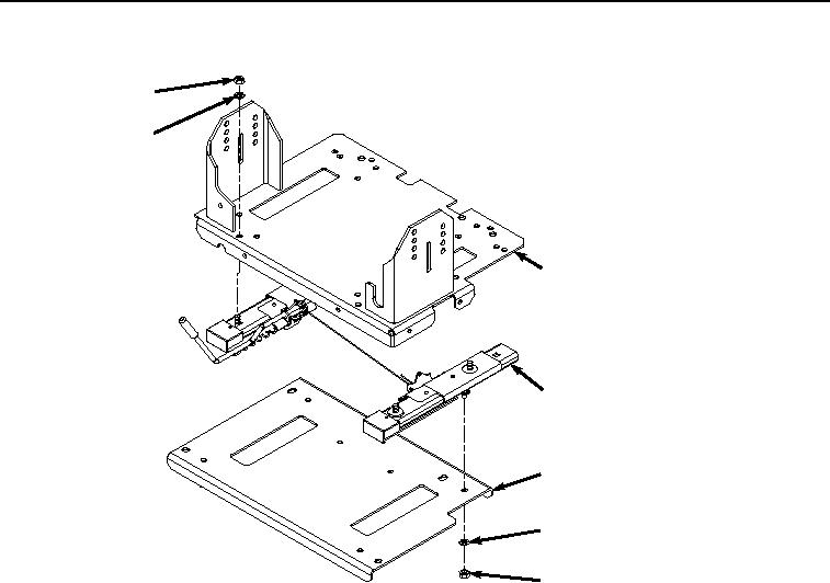
SEAT STAND ASSEMBLY - Continued
47
48
49
50
53
52
51
HYEX02844
Figure 14.
Seat Stand Assembly.
2.
Install base (Figure 14, Item 49) to slide assembly (Figure 14, Item 50) with four nuts (Figure 14, Item 51) and
lockwashers (Figure 14, Item 52).
END OF TASK
SUPPORT INSTALLATION
1.
Install front seat stand support (Figure 15, Item 23) to cab (Figure 15, Item 24) with six screws (Figure 15, Item
45) and washers (Figure 15, Item 46).