• Home
  • Download PDF
  • Order CD-ROM
  • Order in Print
Figure 16. Duct Installation.
Figure 18. Rear Seat Stand Support Installation.

Maintenance Manual For Hydraulic Excavator Type 1 With Hydraulic Thumb And Quick Latch -4 Page Navigation
  701    702    703    704    705  706  707    708    709    710    711  
img
.
TM 5-3805-294-23-4
0581
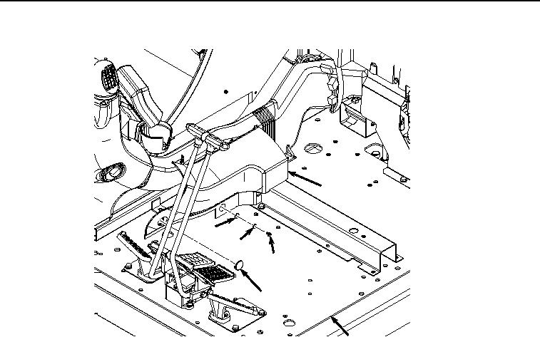
SUPPORT INSTALLATION - Continued
38
41
40
39
37
24
HYEX02037
Figure 17. Duct Cover Installation.
4.
Install cap (Figure 17, Item 37) to cover (Figure 17, Item 38).
5.
Install rear seat stand support (Figure 18, Item 14) to cab (Figure 18, Item 24) with five screws (Figure 18, Item
35) and washers (Figure 18, Item 36).
0581-16


Privacy Statement
Press Release
Contact

© Copyright Integrated Publishing, Inc.. All Rights Reserved.