• Home
  • Download PDF
  • Order CD-ROM
  • Order in Print
Figure 21. Seat Stand Installation.
Figure 23. Right-Hand Console Installation.

Maintenance Manual For Hydraulic Excavator Type 1 With Hydraulic Thumb And Quick Latch -4 Page Navigation
  706    707    708    709    710  711  712    713    714    715    716  
img
.
TM 5-3805-294-23-4
0581
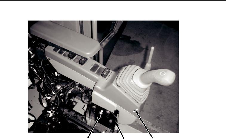
SEAT STAND INSTALLATION - Continued
18, 19
6
20
HYEX02032
Figure 22.
Left-Hand Console Installation.
6.
Install right-hand console (Figure 23, Item 17) to seat stand (Figure 23, Item 6) with three screws (Figure 23,
Item 15) and washers (Figure 23, Item 16).
0581-21


Privacy Statement
Press Release
Contact

© Copyright Integrated Publishing, Inc.. All Rights Reserved.