
TM 5-3805-294-23-4
0581
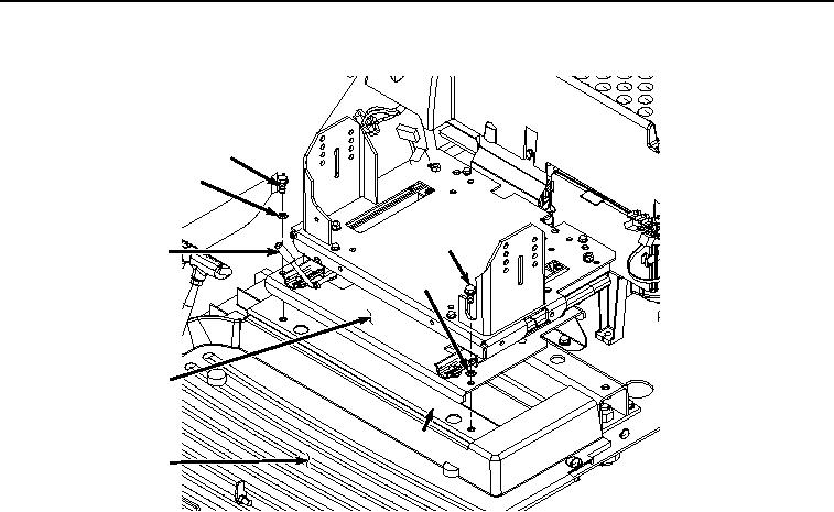
SEAT STAND INSTALLATION - Continued
21
22
21
7
22
6
23
24
HYEX02033
Figure 21. Seat Stand Installation.
3.
Install two screws (Figure 21, Item 21) and washers (Figure 21, Item 22) to seat stand (Figure 21, Item 6) and
front seat stand support (Figure 21, Item 23).
4.
Push lever (Figure 21, Item 7) down and move seat stand (Figure 21, Item 6) forward.
5.
Install left-hand console (Figure 22, Item 20) to seat stand (Figure 22, Item 6) with three screws (Figure 22,
Item 18) and washers (Figure 22, Item 19).