• Home
  • Download PDF
  • Order CD-ROM
  • Order in Print
Figure 22. Left-Hand Console Installation.
Figure 24. Seat Stand Screws Installation.

Maintenance Manual For Hydraulic Excavator Type 1 With Hydraulic Thumb And Quick Latch -4 Page Navigation
  707    708    709    710    711  712  713    714    715    716    717  
img
.
TM 5-3805-294-23-4
0581
SEAT STAND INSTALLATION - Continued
17
15, 16
6
HYEX02031
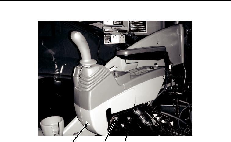
Figure 23. Right-Hand Console Installation.
7.
Install two screws (Figure 24, Item 12) and washers (Figure 24, Item 13) to seat stand (Figure 24, Item 6) and
rear seat stand support (Figure 24, Item 14).
0581-22


Privacy Statement
Press Release
Contact

© Copyright Integrated Publishing, Inc.. All Rights Reserved.