
TM 5-3805-294-23-4
0581
SEAT STAND INSTALLATION - Continued
12
13
12
13
14
6
HYEX02030
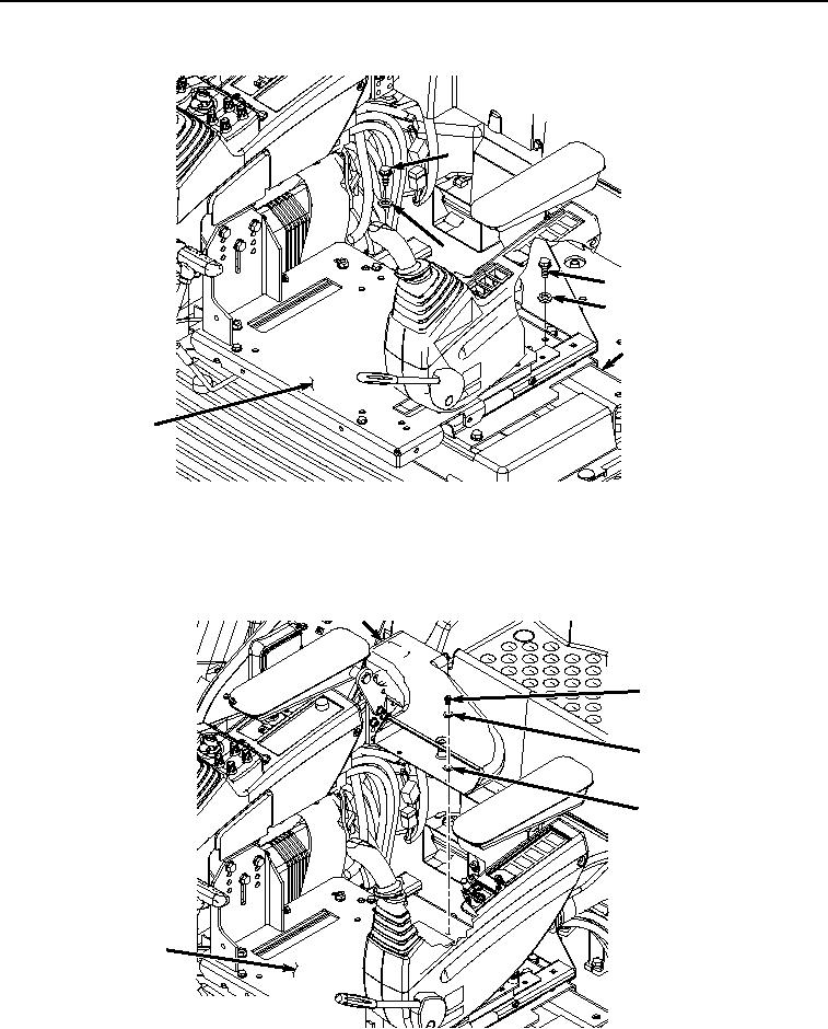
Figure 24.
Seat Stand Screws Installation.
8.
Install air conditioning/heater duct (Figure 25, Item 11) to seat stand (Figure 25, Item 6) with two screws (Figure
25, Item 8), lockwashers (Figure 25, Item 9), and washers (Figure 25, Item 10).
11
8
9
10
6
HYEX02029
Figure 25.
Heater Duct Installation.