
TM 5-3805-294-23-4
0581
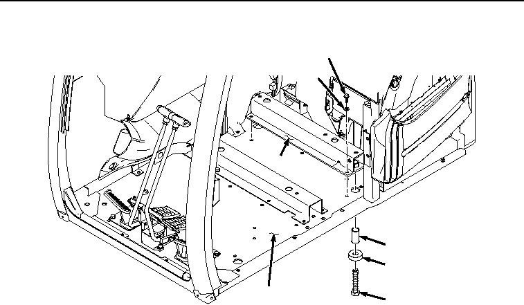
SUPPORT INSTALLATION - Continued
35
36
14
34
33
24
32
HYEX02036
Figure 18. Rear Seat Stand Support Installation.
6.
Install spacer (Figure 18, Item 34), washer (Figure 18, Item 33), and screw (Figure 18, Item 32) to rear seat
stand support (Figure 18, Item 14).
7.
Tighten screw (Figure 18, Item 32) to 406 lb-ft (550 Nm).
8.
Install bracket (Figure 19, Item 27) to rear seat stand support (Figure 19, Item 14) with screw (Figure 19, Item
30) and washer (Figure 19, Item 31).