• Home
  • Download PDF
  • Order CD-ROM
  • Order in Print
Figure 2. Heater Duct Removal.
Figure 5. Left-Hand Console Removal.

Maintenance Manual For Hydraulic Excavator Type 1 With Hydraulic Thumb And Quick Latch -4 Page Navigation
  689    690    691    692    693  694  695    696    697    698    699  
img
.
TM 5-3805-294-23-4
0581
SEAT STAND REMOVAL - Continued
6.
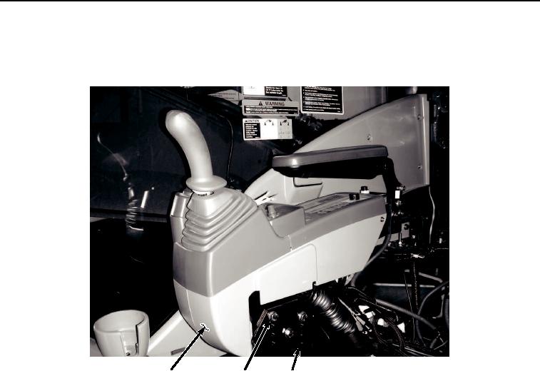
Remove three screws (Figure 4, Item 15), washers (Figure 4, Item 16), and right-hand console (Figure 4, Item
17) from seat stand (Figure 4, Item 6).
17
15, 16
6
HYEX02031
Figure 4. Right-Hand Console Removal.
7.
Remove three screws (Figure 5, Item 18), washers (Figure 5, Item 19), and left-hand console (Figure 5, Item
20) from seat stand (Figure 5, Item 6).
0581-4


Privacy Statement
Press Release
Contact

© Copyright Integrated Publishing, Inc.. All Rights Reserved.